
Loop Configurations
Loop Configurations Explained
Why one size does not fit all
Where there is a need for audio communication to inform entertain or communicate, there is most likely a need for assistive listening. By nature of the environment of each application, the demands on the induction loop system may be very different, requiring a different solution.
Large area coverage, spill control or compensation for signal loss due to metal structures can rarely be achieved with the humble perimeter loop. A knowledgeable, experienced loop designer will consider these performance requirements with installation and budget constraints to determine the most appropriate solution, always mindful that the system must comply with the international performance standard IEC 60118 - 4:2006.
The typical options are :
Universal Access
Loops and telecoils have the potential to provide truly universal access for hard of hearing people here in the UK and throughout the world , but only if they all deliver the same high performance.
To realise this potential, international agreement on the performance of a loop system has been reached and is embodied in the International performance standard for Audio Frequency Induction Loop Systems, IEC 60118 - 4:2006.
This standard defines the magnetic field strength, signal uniformity, frequency response and background magnetic noise for a system. It means that a hearing aid user using a system in a bank, at a train station , at church, in a theatre etc… here or any where else in the world can simply select the T - programme on their hearing aid to relax, participate and enjoy the moment.
An induction loop system that does not deliver standard compliant performance is a missed opportunity. It will not delight customers encouraging them to return and may render the facility in breach of its duty to provide an equal level of access to everyone as set out in the Equalities Act 2010.
Perimeter Loop, Cancellation Loop, Figure 8 Loop, Super 8 Loop or SuperLoop
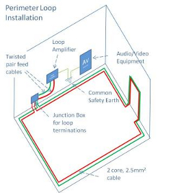
Perimeter loops are the easiest and where they work, the cheapest induction loop configuration to install. They are formed by running 1 or multiple turn loops of cable around the area to be covered.
A twin core cable can be configured using just one core, 2 cores in parallel or 2 cores in series adding performance flexibility
The cable can be concealed behind any non -metallic surface or simply tacked to the skirting board. However, it should never be installed at the same height as the hearing aid ie the listening plane. In fact, the further displaced from the listening plane, the more uniform the field strength will be.
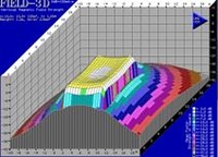
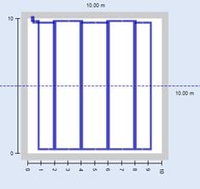
Perimeter Loop
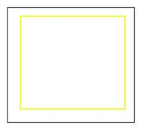
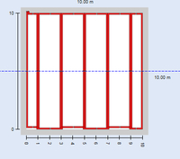
The yellow line represents the perimeter loop
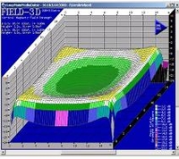
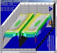
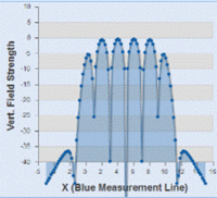
3D Plot showing relative dip of field strength in the centre of the loop
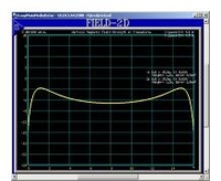
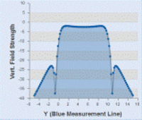
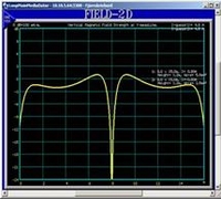
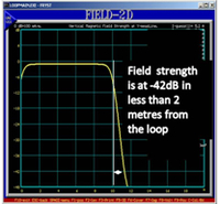
2D Plot showing relative dip of field strength in the centre of the loop
Remember
Never install a Perimeter Loop at the listening Height
The IEC standard states that the signal strength at the listening height must be 0dB ±3dB and must remain within
these limits throughout the listening plane. So whether the hearing aid user is in the middle of the room or close to the wall, they will receive a useable signal without the need to adjust the sensitivity of their hearing aid.
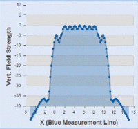
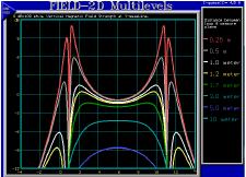 The graph on the right shows the variation of field strength across the centre of a room at a range of listening distances from a perimeter loop. The red curve shows the field strength at a vertical distance of 0.25m from the loop.
In the centre of the room the field strength is -1dB, but at the edge of the room it has increased to over +9dB.
The variation in field strength exceeds that permitted by the
standard illustrating why a perimeter loop must not be
installed at listening height.
The further the loop is displaced from the listening plane, the flatter the response becomes, leading to some more simple rules of thumb.
- If the Loop is to be installed in the floor for seated use, (Listening plane of 1.2m) the maximum width of the loop is in the order of 22 metres. (No construction metal present)
- If the Loop is to be installed in the floor for standing use (Listening plane of 1.7m, the maximum width of the loop is in the order of 26 metres. (No construction metal present)
- By installing the loop at a greater distance than 1.7m, from the listening plane, the simple perimeter loop can be used to cover larger spaces. This principle is often exploited to cover churches and cathedral size spaces, by installing the loop on the triforium or even externally on the roof.
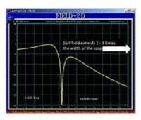
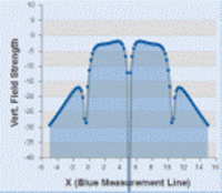
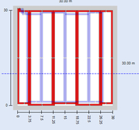
2D Plot showing the spill field of a perimeter loop
Remember
A perimeter loop has a spill field 1 - 2 times its width
Spill field is the name given to the signal generated by the system that exists outside of the induction loop.
Magnetic fields fall off very rapidly with distance, however, 1 - 2 times the width of the loop away, a signal level greater than - 32dB may still be present.
That means a loop 5m wide may still be radiating above the acceptable background noise level 5m - 10m away.
Note: - 32dB is the maximum level of background magnetic noise that the standard IEC 60118 - 4:2006 deems acceptable and is used by UnivoxAudio as a reference to define spill control
Remember
Construction metal in the same plane as the loop can absorb the signal.
This absorption or loss of signal is dependent on the proximity of the metal to the loop, the amount and its conductivity. Aluminium is more lossy than mild steel and stainless steel with the highest resistivity causes little or no loss. The phenomenon is also frequency dependent.
To overcome this issue, the first option is to drive more current through the loop and correct the frequency response. With the Power of Univox® and the MLC or tone control featured on all our standard amplifiers, this can work well for small perimeter loops.
The second choice is to move the loop further away from the metal. For example, installing the loop at ceiling level instead of around the floor, assuming that there is no construction metal in the ceiling. A false ceiling using tiles on an aluminium frame may be very lossy depending on its age.
Where the loss is too high and the signal too variable (signal variation across the listening plane is more than 6db), smaller multiple loops must be used if the system is to comply with IEC 60118 - 4:2006.
Note: Metal loss correction is only capable of correcting the frequency response at a single given point. For larger loops, this can mean that some areas will still remain with insufficient compensation whilst others may be over compensated hence the need to use smaller multiple
construction metal in proximity to a perimeter loop will restrict the maximum viable loop width.
If the width of the area to be covered is larger than this a different loop topology should be used
| Floor or ceiling Type | Max. loop width Listening plane 1.2m from Loop | Max. loop width Listening plane 1.7m |
|---|---|---|
| No metal in floor | 22m | 26m |
| Standard reinforced concrete | 6-10m | 5m to 9m |
| Heavy reinforced concrete | 3-6m | 2-5m |
| Metal system floor or Steel deck | 1-3m | 2-3m |
| Suspended ceiling Glass/Metal | 3m | 3m |
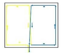
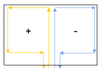
Cancellation Loop
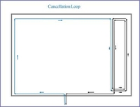
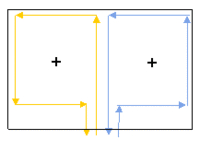
A single cable is configured to form 2 loops of different sizes using a figure 8 pattern.
Spill field for Cancellation Loop.
Spill field for Perimeter Loop
Cost effective Spill Control
A cancellation loop is a simple and cost effective way of controlling the spill field in 1 or 2 directions. In its simplest form, it is a figure 8 loop where the ratio of the 2 areas circumscribed by the cable are such that the magnetic fields extending beyond the loop in 1 direction cancel, as shown in the diagram.
This design is simple to install and relatively low cost using just 1 induction loop amplifier. However, the cancellation loop is generally installed in the room so not all of the space in the room will have standard compliant coverage.
Installing a cancellation loop along a second side of the room will reduce the area coverage in the room further, but in some circumstances, it is still more convenient than using Univox SuperLoop Series® technology.
The exact induction loop area ratios to achieve optimum cancellation of magnetic field can be found by trial and error or by using a software based design tool.
Cancellation loops can also be designed using an anti-phase Super 8 (+ -)loop or by driving 2 independent loops with different current values, either by using 2 separate induction loop amplifiers or a custom designed ratio transformer.
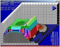
Figure 8 Loop
A single cable is configured to form 2 or more loops generally of the same size using a figure 8 pattern.
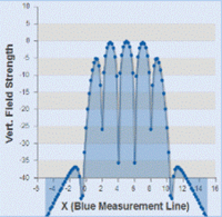
The adjacent segments are opposite in phase creating a null field where the sections intersect.
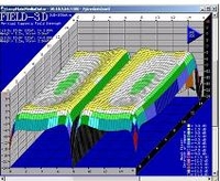
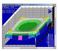
The 3D - field strength plot shows the 2 distinct areas covered by this loop configuration.
With both loops of equal size, the field patterns of the 2 segments are a mirror image.
Basic Compensation
In applications where there is significant signal loss due to construction metal or a very large area to be covered, the simple figure 8 loop configuration can provide a cost effective and simple solution.
The standard figure 8 loop is, as you would imagine, a figure 8 pattern of wire. It is made from a single continuous cable and can be 2 or more segments long. It is installed in or on the floor or ceiling.
By dividing the area into smaller, usually equal size segments, it is possible to achieve good uniformity of signal within each segment with a lower drive current. However, since more cable is used, a higher drive voltage will be required.
The voltage headroom of the amplifier and cable type will limit the number and size of the segments in this configuration.
Unfortunately, where the cables of the 2 adjacent segments run next to each other there is field cancellation to the extent that there is a null or no signal for the hearing aid.
In practice, this design is best suited to applications where the seating is fixed in which case, the parallel runs of cable can be kept in the aisles where no signal is required.
This loop design offers improved spill control; along the narrow ends of the loops, the spill is reduced to approximately one loop width, along the other sides, it is 1 to 2 times the loop width. The smaller the width of the loops, the better the control.
Note: The spill field in the horizontal plane is smaller compared to a perimeter loop covering the same total space
Super 8 (++) Loop
Up to 4 separate loop cables are configured to cover the space and connected to a single Univox amplifier in parallel.
In the Super 8 ++ Loop configuration, the segments are in phase. The resulting field pattern is identical to a perimeter loop offering the same total area coverage.
Spill control for the Super 8 (++) loop is identical to the equivalent perimeter loop
The Power of Univox
This loop configuration is a proprietary design unique to Univox® Taking advantage of the higher output current capacity of the Univox® product range. (See Power of Univox®)
On first inspection, a Super 8 loop™ looks like a standard figure 8 loop, creating a similar pattern on the floor or ceiling where it is installed.
However, that is where the similarity ends. Each segment of a Super 8 Loop™ is connected directly to the amplifier ie. in parallel taking advantage of the extra high output current of the Univox® Amplifiers
A Super 8 Loop™ can be configured in 2 ways, either with the segments in phase (++) or antiphase (+ - ) with all Univox® amplifiers capable of driving up to 4 segments.
In Phase Super 8 (++)Loop™ System
The In-phase Super 8 (++) Loop™ system extends the range of the Perimeter loop.
With this configuration, the magnetic field attributed to the conductors running next to each other from adjacent sectors cancel, effectively giving the same performance as a perimeter loop covering the whole space.
Whilst the output current required may be several times as much, significantly, the output voltage equired is reduced by almost the same amount making it practical to cover an area of up to 1800m2 with a single Univox® induction loop amplifier.
Note: The difference in feed cable lengths may cause 1 or 2dB variation in field strength between segments, but standard compliance is still achievable.
Using software simulation Super 8 Loop design is simple, providing affordable solutions for large area coverage
Super 8 (+-) Loop
Up to 4 separate loop cables are configured to cover the space and connected to a single Univox amplifier in parallel.
The big brother of a standard figure 8 loop
As previously stated, a Super 8 Loop™ can be configured in 2 ways, either with the segments in phase (++) or antiphase (+-) with all Univox® amplifiers capable of driving up to 4 segments.
The out of-phase Super 8 (+-) Loop™ system complements the figure 8 loop.
With this configuration, the magnetic fields attributed to the conductors running next to each other from adjacent sectors interact producing a null field identical to that associated with a standard figure 8. The output current required may be several times as much, but the output voltage is reduced by almost the same amount.
Univox® amplifiers all feature a high output voltage, however, due to safety considerations even the largest are limited to 50V. In applications where the impedance of the perimeter or figure 8 loop is too high, a Super 8 (+-)Loop may be a viable alternative.
Design Flexibility
The Super8 loop can be quickly reconfigured from (Super 8 (++) to Super 8(+-). or vice-versa. Furthermore, each individual loop can be driven by a separate amplifier if required, providing the installer with a range of options to optimise the system.
The Super 8(+-) configuration is ideally suited to fixed seating applications where the voltage headroom of the amplifier is insufficient to drive a standard figure 8 loop.
The feed cables can be selected to maintain equal impedance of each loop if required
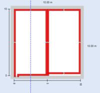
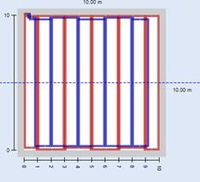
SuperLoop
2 independent figure 8 loops, A master and Slave represented by the red and blue lines.
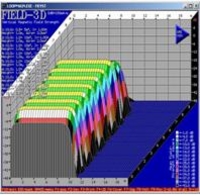
The 3D plot opposite shows the field pattern of just one arm of the array.
A SuperLoop system can provide excellent attenuation of the spill field
To cover large areas, compensate for the effects of metal and or control spill, a range of different induction loop configurations can be used. The choices are Figure 8 loop, cancellation loop, Super 8 Loop™ and SuperLoop™
The SuperLoop™ exceeds the performance of all other induction loop types in every respect. A standard SuperLoop provides metal loss compensation, large area coverage, ultra-low spill performance, and a highly uniform magnetic field in the vertical and horizontal planes ( when facing the long sides of the loop segments) i.e Near 3D area coverage. The design principles are quite simple and made even easier with the Univox® SuperLoop™ Calculator or our latest software.
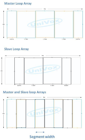
A SuperLoop comprises 2 independent figure 8 loops driven by separate amplifiers with a 900 phase shift of the input signal. The larger figure 8 loop is the master loop array and the smaller is the slave array. By applying this phase shift, the associated magnetic fields are uncorrelated ie they do not interact with each other.
Uncorrelated Magnetic Fields
Master Loop Array
Magnetic field of Master Loop Array
Note the position and magnitude of the peaks generated by the Master Array
Slave Loop Array
Magnetic field from Slave Loop Array
Note the position and magnitude of the peaks generated by the Slave Array
Master and Slave Loop Arrays
Resultant magnetic field for Master and Slave Loop Array
Note how the 2 magnetic fields combine. The highest wins
Loop Configurations and their properties compared
| Feature | Perimeter Loop | Figure 8 Loop | In Phase Super 8 LoopTM | Antiphase Super 8 LoopTM | SuperLoopTM | Cancellation Loop |
|---|---|---|---|---|---|---|
| Design | Simple | Simple | Simple | Simple | Simple with software | Trial and error or simple with software |
| Installation | Simple | Moderate | 1.Moderate | Moderate | Hardest | Moderate |
| Suitable for large area coverage | Limited to a maximum loop width of 22m (n1) | Yes | As Perimeter Loop (n3) | Yes | Yes | No |
| Suitable for areas with construction metal | No Loop width must be reduced | Yes | No Loop width must be reduced | Yes | Yes | No Loop width must be reduced |
| Achievable area Coverage | 100% | Null fields where adjacent segments meet | 100% | Null fields where adjacent segments meet | 100% | The cancellation loop limits the max achievable area coverage to approx. 75% |
| Spill Control | 1to 2 times loop width | 1 to 2 x segment width along length of loop.1 x segment length along width of loop | same as equivalent perimeter loop | Same as equivalent figure 8 loop | Excellent To 1. 4m in horizontal plane 4m in vertical plane | Depends on design, but only practical for spill control in 1 or 2 directions. |
| Signal uniformity | Acceptable in Horizontal Plane | Acceptable in horizontal plane, but will have null fields | Acceptable in Horizontal Plane | Acceptable in Horizontal Plane, but will have null fields | Excellent in horizontal plane and vertical plane (facing the long loop runs) | Acceptable in horizontal plane. See 'Achievable coverage' |
- n1 For a field strength variation across the listening plane no worse than 6 db, the maximum loop width for a perimeter loop displaced 1.2m from the listening plane is approximately 22m. Construction metal in close proximity to the loop will dramatically reduce the maximum loop width.
- n2 Spill control is defined as the distance from the loop at which the magnetic field has reduced by 32dB. (This level is still audible. It equates to the acceptable level of background magnetic noise permitted in the standard.
- n3 The in-phase Super 8 ( + + ) Loop is limited to the same maximum width for the area to be covered as a perimeter loop


