21st Century Sound For Places of Worship
Speech Intelligibility for Places of Worship.
Traditional places of worship are notorious for poor acoustics degrading the intelligibility of the spoken word. Ironically, for the hard of hearing we have largely solved the problem with the development and continuous improvement of induction loop systems. However, for the majority, with apparently good hearing, little has been done to improve the intelligibility of sound in these highly reverberant environments.
Delivering services in the mother tongue of the congregation arguably increases the need for greater clarity and intelligibility of speech; the Catholic church switched from Latin to English Mass in the UK back in 1964. Slowly over the decades, we have seen the introduction of reinforced sound in these environments, but with mixed success. The classic building for worship is highly reverberant producing a vibrant cocktail of sound. Whilst this enriches the sound of music and song it has a devastating effect on speech and can destroy any intelligibility.
The issues are multifaceted. Some reverberation can be beneficial: the trained orator can take advantage of it defying the inverse square law and projecting intelligible speech to the back of the congregation without deafening those in proximity. Too much reverberation, however, and the speech is blurred lacking any clarity regardless of the volume

Early audio systems used in places for worship comprised of not much more than a couple of speakers, an amplifier and a microphone. Raising the volume was the prime objective; everyone could hear the service. Unfortunately, they could not necessarily decipher what was being said.
Higher volume means everyone can hear, but from a point source such as a conventional speaker the volume falls according to the inverse square law so the volume at the speaker needs to be very high for those at the back to hear. This just exacerbates the problem. Reverberation is not resolved and sound levels are too variable for comfortable listening.

A solution is to use multiple speakers down the length of the building creating zones. Each speaker covers a small range, so it is not too loud for those close to, but it has sufficient level for those at the back of the zone to hear. However, using multiple speakers in this way leads to more sound blurring. The problem of reverberation is still there, and additionally, sound from the first zone spilling into the next zone will be delayed as a consequence of the distance between the speakers. It may not be reverberant sound, but it has the same result-reduced intelligibility.
To overcome this problem a delay is introduced between zones. Now the system is becoming quite complex! Each zone needs to be wired to a separate amplifier with a different (delayed) audio feed.

The soundscape has been improved but nothing has been done to tackle the fundamental issue of long reverberation times typically caused by the high ceilings with reflective surfaces. Acoustic tiles and other physical remedies could be used to dampen the reflections, but these would detract from the aesthetic and impede the musical richness of the space. Instead we turn to column speakers. Long and thin, these elegant speakers easily blend into the architecture of a high-ceilinged venue and, by nature of their construction, dispersion in the vertical plane is restricted; a longer column will offer narrower dispersion in the vertical plane. By tilting the speaker, the sound reaching the ceiling is further reduced and concentrated onto the congregation. In addition, the volume of the sound no longer reduces in accordance with the inverse square law, the speakers can project sound over much longer distances meaning fewer zones or no zones at all!
Mounting the speaker at an angle can be obtrusive. By controlling the signal to each driver in the column, the sound beam can be steered and focused onto the congregation whilst the speaker remains in a vertical position. An aesthetically pleasing acoustic solution for highly reverberant environments.
Unfortunately, the challenge is not complete. With multiple
speaker drivers, zones, time delays and possibly beam steering, instead of a small twin core cable daisy chained to connect each speaker, a large multicore cable connecting each speaker back to the control room is required. Not only is this expensive to install, in listed buildings with stone and decorative plaster work it may not even be permitted
Fulgor Services are the only manufacturer providing a solution; steerable column speakers with power, signal and control all on a twin core cable.

Fulgor services specialise in the design and manufacture of audio systems for places of worship and have systems installed in many of the most iconic religious venues on three continents. They offer attractively styled passive column speakers and control systems like many manufacturers, but they also have a range of active column array speakers. These speakers have built in amplifiers and signal processing providing volume control, equalisation, time delay and even beam steering. Using a unique power supply that carries both power and audio signal on just 2 wires in many venues there is often no need to install new cables as the existing speaker cables will do even if they are daisy chained. Where new cabling is required, it is only a single twin core 1mm2 cable which is easy to install and conceal.
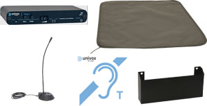
Induction Loop Systems
Your venue needs a standard compliant induction loop system to guarantee access for your hard of hearing members and guests.
Hard of hearing people find it particularly difficult to distinguish between background noise and the speech that they want to listen to. Reverberation is background noise, acceptable levels of reverberation for someone with good hearing are much higher than those for someone who is hard of hearing. No matter how much improvement we can make to the levels of reverberation and other sources of background noise it is unlikely to be good enough for the hard of hearing. Instead we rely on assistive listening technology such as induction (hearing) loops. All assistive listening technologies work on the same principle, they filter out the background noise and deliver just the wanted sound to the listener.
If you want to speak to someone in a crowded noisy room, you will get a little closer to them and speak directly into their ear, and that is exactly what happens when you use an induction (hearing) loop system. When you speak into the microphone of an induction (hearing) loop system it is like speaking directly into the persons ear.
The microphone provides a high level of rejection to the background noise and just conveys the wanted speech.
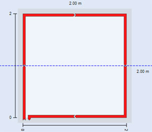
In the simplest form of induction (hearing) loop system, the speech is converted into a current which is driven round a loop of cable encompassing the venue. The current sets up a magnetic field which in turn induces a current into the pick-up coil (T-coil) of the person’s hearing aid. This current is amplified and tonally corrected for the individual’s hearing loss and fed into their ear via the speaker in the hearing aid. Induction loops are not only universal, they are the only assistive listening technology that provide a customised signal tailored to everyone’s hearing loss.
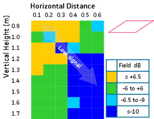
Perimeter loops are not always the best solution. There are many other loop configurations that may be more appropriate to meet the requirements in your venue eg. Figure 8, Cancellation, Super 8, super loop etc.


Univox Audio Ltd is a specialist distribuotor. We believe that good communication is core to any organisation. To help you acihieve the best levels of speech intelligibiliy we have selected the best, affordable Induction loop, Infrared, FM and speaker systems available. But rather than leave anything to chance we also provide training for installers to help them specify and design.
Ask your installer about Fulgor Activo Speakers and bring your sound system into the 21st century without the inconvenience and expense of installing specialist cables.
Need Help to Find an Installer? Call or Email Us and we will put you in touch with a competent Pro Audio Installer.
T:010707 339216 E: info@univoxaudio.co.uk
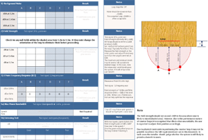
 Test Conditions
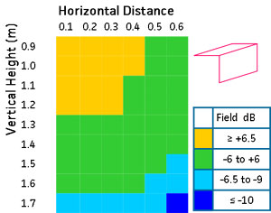


 programmable, its mode of operation can be updated to reflect changes to the standard as they occur. The instrument has a clear, backlit, LCD display and steps through the required measurements in a logical sequence, matching the test certificate to simplify the certification process.
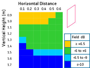
 The Univox loop listener uses a peak detector so it can easily be used to check the field strength level of live signals. With test signals you would expect to see the green led lit indicating that the field strength is at least 0dB. When you connect the live signal you would expect the green LED to flicker on the peaks of the signal with the orange LED flickering occasionally too. If neither LED flickers, the field strength has dropped to below -6dB.


