Portable Loop Systems

Portable loops – do they ever make sense?

There are two basic types of portable loop, the most common is the one to one portable loop often sold for use at counters or for one to one meetings. The other is much larger and is intended to provide temporary coverage of a hall or meeting room. They are both offered as convenient, low cost alternatives to fixed installations and where used appropriately, they will not disappoint. The key is in understanding their practical and technical limitations.

One to One Portable loops

The one to one portable loop is rechargeable and typically half the size of a briefcase. It will have a built in omni-directional microphone (picks up sound equally from all directions) and loop. The unit is designed to be left on charge, perhaps on its purpose built wall bracket and in theory is always ready.In use, it must be positioned between the two users on a flat surface, such as a counter or desk. The field pattern and uniformity is dependent on the size and orientation of the loop, typically vertical. Smaller loops will exhibit poorer signal uniformity and cover a smaller volume of space. However, even the larger most powerful units will only provide a compliant sweet spot within 400mm or so.

The omni- directional microphone and its positioning are also less than ideal. Hard of hearing people find it difficult to separate the background noise from the wanted signal. Assistive listening systems only work well when they do this for them.They need to filter out the back ground noise and provide a clear intelligible signal to the hearing aid. To achieve this, a directional microphone positioned as close as possible to the person speaking should be used. The omni-directional microphone in the case of the one to one portable loop will pick up much of the background noise, mix it with the wanted speech and deliver this sound cocktail to the hearing aid. Arguably, nothing has been achieved, but if the user had a more capable hearing aid he may actually be worse off.

Regardless of the questionable performance of the typical one to one portable loop systems offered, the practical advantages are also compromised in the most common application. Possibly to save a relatively small amount of money and avoid the inconvenience of installation, one or two portable loops are often purchased to cover a few counters.

This presents some practical issues and is not in the spirit of the old DDA legislation or the current Equalities Act 2010. It is still discriminatory, it is not good for hard of hearing people and it represents a poor deal for the service provider.

Consider the following scenarios; the hard of hearing customer arrives at the counter, there is no fixed loop, he does not want to admit he is disabled, so he tries to engage with the assistant, she explains once, twice, three times, speaking louder and louder, he does not understand, he’s embarrassed, she’s embarrassed and the queue is building. Or, perhaps he does ask to use the portable loop, she leaves the counter, finds the portable loop system, but can’t remember how to use it, she finally gets it working, she’s embarrassed for the delay, he‘s embarrassed for asking and the queue is building.

With a fixed, standard compliant, induction loop system at the counter, the hard of hearing person, would have switched their hearing aid to the T-position, made their transaction at the counter, like anyone else, without any delay, embarrassment or inconvenience, for them, the staff and other members of the public. Everyone would have derived a benefit from the system with customer satisfaction maintained.

The practical and technical limitations of the one to one portable loop system do not mean that it has no place in the market. The better units can be used with an external lapel microphone for improved background noise rejection. They are best suited to applications where portability is fundamental. A mobile location for example, or by visiting professionals such as social and healthcare workers. Portable loops have been used extensively and to good effect in doctor’s surgeries, consultation rooms, hospitals, audiology departments, libraries and in education and social work where the appropriate consideration has been given.

Their poor reputation stems from the overreliance placed on them by many service providers, particularly retailers who view them as a quick, cost effective way of ticking a box and meeting their obligations under legislation when, in fact, for many of the reasons outlined, they provide very little if any benefit to the hearing aid user.

Choosing a one to one portable loop system

A one to one portable loop system will be chosen for its portability, but other parameters must not be overlooked. Use the check list table 1 as a guide.

Choosing a one to One Portable Loop system Check List

Consideration Comments
Is it small, lightweight and robust? If it is too small the magnetic field will be too variable and localised (A height and width approx. 300mm is OK, the depth is not important but it must have a firm stable base)
Is it easy to carry? Some units double as a carry case
Is there storage space for the charger, an external microphone loop listener and operating instructions? The accessories need to travel with the loop system for true portability. Remember, it is the gross weight of the system that is important.
Is it rechargeable? Need at least 8 hours use between charge
Does it have a battery charge status? Knowing just how much charge is left in the system is very useful
Are the batteries sealed? There must be no possibility that the batteries could leak
What is the battery charger type? Switch mode battery chargers are smaller and lighter than transformer based chargers
Can it deliver a field strength of 400mA/m rms at a distance of 600mm or greater? The uniformity of the field strength is also an issue. If small movements of the head lead to a dramatic change in field strength, the system will be impractical to use. It is a good idea to check it yourself.
What is the operating bandwidth? It should be at least 100Hz to 5KHz
Does it have Automatic Gain Control (Compressor)? This feature is essential. It Keeps the output level within a comfortable range for the user regardless of the input level
Does it have a remote microphone socket? To get the best out of the system the microphone must be as close as possible to the person speaking, making an external microphone essential
Is an external microphone included? This should form part of the system (not an afterthought
Is a loop listener Included? The user will need some means of checking that the system is working. ( This can be bought separately)
Good sound clarity – low distortion? It must be capable of maintaining good intelligibility.
Is the unit clearly marked with hearing logo? It should be obvious what it is
Is there an auto cut off to conserve the battery? Nice feature, but not essential

Portable Room Loop Systems

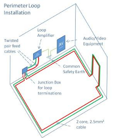
A portable room loop is a complete perimeter loop system in a carry case. The case, typically a flight case has a loop amplifier built in and is supplied with a loop cable and at least 1 microphone as standard. In addition it should include a loop listener/tester since, with each deployment of the system, some adjustment to the output will be required if the performance standard is to be met.

It can provide a cost effective, quick fix, temporary or possibly permanent solution to hearing accessibility satisfying the Equalities Act 2010 and similar legislation worldwide.

If you manage several small to medium size meeting rooms that are rarely used or you travel to different venues to deliver presentations, then a portable room loop is a practical, permanent solution. However if you have one or more meeting rooms that are constantly in use then the portable room loop should probably be viewed as a short term solution, perhaps until there is sufficient budget to make fixed installations and the rooms are due for refurbishment.

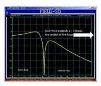
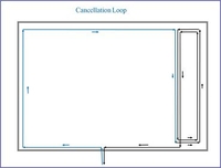
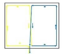
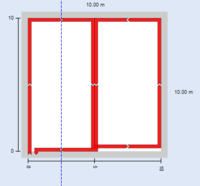
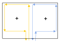
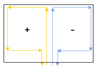
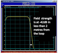
With a fixed installation, the loop is always there and hopefully, always on. Whilst a well-designed portable system will not take long to deploy and set up, it does require continuous management, which over time will add considerable cost and irritation to the business. Furthermore, a portable room loop uses a perimeter loop, this has a significant spill field meaning that 2 or more systems cannot be used in adjacent rooms simultaneously and it is unsuitable for confidential meetings. In addition, the loop performance can be restricted by constructional metal in the building. A SuperLoop system, a special type of induction loop system, overcomes all of these issues, but it must be installed.

Choosing a portable room loop

To select the most appropriate portable loop system for your venue you need to understand where and how the system will be used.

The Rooms

The sizes of the different rooms that the system will be used in provide a guide to just how powerful the system needs to be. Ideally, the system will be capable of covering the whole area of the largest room, but in any event, no less than 30% of the space should be covered as a guide.

ROOMSCommentsNotes
How many locations will the portable room loop be used in? If it will be used in several rooms that are in frequent use you may need more than one system?
How big are the rooms?Choose a system that is capable of covering at least 30% of the largest space. L = ………… W=……… A=………..

The actual area coverage that a loop system can achieve will be reduced by the amount and type of metal in the floor construction as metal absorbs the signal.

Use the pictures below to help identify the type of building or floor construction where the system will be used.

The de-rating factors given are only valid for Univox® Amplifiers. Other manufacturers should be able to provide similar data.

1. Non-metallic e.g. wood or stone

Area Coverage does not need to be de rated as there are no losses. (Area coverage for the Univox® PL-2 = 150m2 )

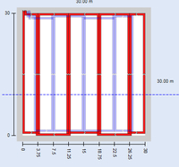
Max loop width =20m. This assumes the loop is laid on the floor and the listening height is at 1.2m from the ground. If this width is exceeded, the signal strength in the middle of the room will be lower than the standard permits

2.Standard reinforced concrete

De-rate area coverage by 20% to compensate for signal loss (Area coverage for the Univox® PL-2 approx. 120m2)

Maximum loop width = 5m to 7m. If this width is exceeded, the signal strength in the middle of the room is likely to be lower than the performance standard permits and metal loss or tone control will not be capable of providing uniform compensation over the whole space

3. Heavy reinforced concrete

De rate are coverage by 30% (Area coverage for the Univox® PL-2 approx. 105m2)

Maximum loop width = 5m If this width is exceeded, the signal strength in the middle of the room is likely to be lower than the performance standard permits and metal loss or tone control will not be capable of providing uniform compensation over the whole space

4. Metal Raised Access Floor

De rate are coverage by 50% (Area coverage for the Univox® PL-2 approx.75m2)

Maximum loop width = 4m. If this width is exceeded, the signal strength in the middle of the room is likely to be lower than the performance standard permits and metal loss or tone control will not be capable of providing uniform compensation over the whole space

5. Metal System Floor

De rate are coverage by 50% (Area coverage for the Univox® PL-2 approx.75m2)

Maximum loop width = 4m. If this width is exceeded, the signal strength in the middle of the room is likely to be lower than the performance standard permits and metal loss or tone control will not be capable of providing uniform compensation over the whole space

6. Glass and metal construction

De rate are coverage by 50% (Area coverage for the Univox® PL-2 approx.75m2)

Maximum loop width = 4m. If this width is exceeded, the signal strength in the middle of the room is likely to be lower than the performance standard permits and metal loss or tone control will not be capable of providing uniform compensation over the whole space

The maximum loop widths given are indicative and valid for any perimeter loop system.

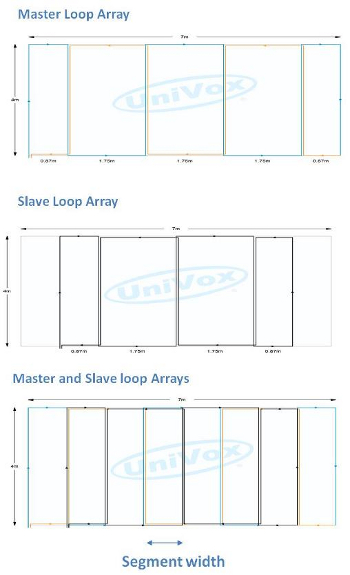
Note: By laying the loop cable in a figure 8 pattern, the maximum loop width can be maintained for larger spaces.

Background Magnetic Noise

An induction loop system will not provide a benefit to hard of hearing people where the level of background magnetic noise is too high. Where possible, check the level of background magnetic noise in each of the intended locations for the portable loop system before purchase. (It should be less than -32dBA) UnivoxAudio and our partners will be pleased to help.

How Are the Rooms Used

To specify the appropriate accessories for the portable loop system it is necessary to understand how the rooms are used and what, if any, audio visual equipment is used in each. If there is a sound reinforcement system in each of the rooms, check that they have line level outputs which are easy to access. In this case, additional microphones may not be necessary. However, the Portable loop system will need at least 1 line level input and a suitable interconnecting. Where none or only some rooms have sound reinforcement, microphones must be specified with the portable loop system. In which case consider the following;-

  • Do the presenters stand in one place?

A wired microphone may be suitable

  • Do the presenters move around the room or present from different locations in the room?

A radio microphone may be the most practical. You can choose a held or headset/lapel type. Note: Holding a microphone for any length of time can be fatiguing

  • Is audience participation required?

A second radio microphone may be required. A hand held microphone is the most appropriate for this purpose.

  • Are there any other audio sources such as a DVD player or television in any of the rooms?

Check that the line output from the source(s) is easy to access. The Portable loop system will need a spare line input to make this connection.

Portable Room Loop product Check List

Use the check list (table 3) to guide you to your optimum Portable Induction Loop system.

Portable Room Loop product Check List (Table 3)

Consideration Comments
What is the Square Area Coverage of the system? Is the square area coverage of the system sufficient for your rooms and building construction?
Is the case small, lightweight and robust? There should be a dedicated space for each piece of equipment and accessory in the case. This makes it easier to check that everything has been packed away. It also keeps everything tidy and well protected.
Will it be easy to carry? A flight case with wheels is a good practical option. Remember, it is the gross weight of the system that is important
What power supply is required? For use in the UK 230V ac operation is required
Is the amplifier built into the case? With the loop amplifier built into the case, the system will be much quicker to set up. Some systems are simply standard amplifiers offered in a carry case
Are the controls, inputs and outputs easy to access? Important for ease and speed of setup
How many line and microphone inputs are there? Refer to the section ‘How are the rooms used’ to confirm what inputs are required. Ideally, the inputs will be balanced to provide better immunity to electrical interference.
What is the operating bandwidth? To meet the performance standard IEC60118-4 it should be no less than 100Hz to 5KHz
Does it have Automatic Gain Control (Compressor) This is an essential feature. It keeps the output level within a comfortable range for the user regardless of the input level
What length is the loop cable and how is it stored? The loop cable should be wound on a spool with both endsterminated in a plug. This will keep the cable tidy and protected when not in use. It will also facilitate quick deployment and retrieval. For best performance the cable should be non-inductively wound on the spool. This helps to maintain the frequency response of the system when operated with some cable still on the spool.
Accessories To get the best out of the system the microphone must be as close as possible to the person speaking, making an external microphone essential
How many microphones are required? Refer to the section ‘How are the rooms used’ to confirm how many and what type of microphones will be most suited. It is advisable to include at least 1
Is a battery charger included? If you choose wireless microphones, a suitable battery charger should be included with the system
How do I check the field strength? A loop Listener/field strength indicator must be included with the system
What consumables are required? None, however, it is good practice to tape the loop to the floor to prevent it from becoming a trip hazard.Gaffer tape provides a practical solution.

Planning

Installation

Loop Configurations

Loop Configurations Explained

Why one size does not fit all

Where there is a need for audio communication to inform entertain or communicate, there is most likely a need for assistive listening. By nature of the environment of each application, the demands on the induction loop system may be very different, requiring a different solution.

Large area coverage, spill control or compensation for signal loss due to metal structures can rarely be achieved with the humble perimeter loop. A knowledgeable, experienced loop designer will consider these performance requirements with installation and budget constraints to determine the most appropriate solution, always mindful that the system must comply with the international performance standard IEC 60118 - 4:2006.

The typical options are :

Universal Access

Loops and telecoils have the potential to provide truly universal access for hard of hearing people here in the UK and throughout the world , but only if they all deliver the same high performance.

To realise this potential, international agreement on the performance of a loop system has been reached and is embodied in the International performance standard for Audio Frequency Induction Loop Systems, IEC 60118 - 4:2006.

This standard defines the magnetic field strength, signal uniformity, frequency response and background magnetic noise for a system. It means that a hearing aid user using a system in a bank, at a train station , at church, in a theatre etc… here or any where else in the world can simply select the T - programme on their hearing aid to relax, participate and enjoy the moment.

An induction loop system that does not deliver standard compliant performance is a missed opportunity. It will not delight customers encouraging them to return and may render the facility in breach of its duty to provide an equal level of access to everyone as set out in the Equalities Act 2010.


Perimeter Loop, Cancellation Loop, Figure 8 Loop, Super 8 Loop or SuperLoop

Perimeter Loop Install

Perimeter loops are the easiest and where they work, the cheapest induction loop configuration to install. They are formed by running 1 or multiple turn loops of cable around the area to be covered.

A twin core cable can be configured using just one core, 2 cores in parallel or 2 cores in series adding performance flexibility

The cable can be concealed behind any non -metallic surface or simply tacked to the skirting board. However, it should never be installed at the same height as the hearing aid ie the listening plane. In fact, the further displaced from the listening plane, the more uniform the field strength will be.

Perimeter Loop

perimeter loop

The yellow line represents the perimeter loop

center dip

3D Plot showing relative dip of field strength in the centre of the loop

center dip 2D

2D Plot showing relative dip of field strength in the centre of the loop

Remember

Never install a Perimeter Loop at the listening Height

The IEC standard states that the signal strength at the listening height must be 0dB ±3dB and must remain within these limits throughout the listening plane. So whether the hearing aid user is in the middle of the room or close to the wall, they will receive a useable signal without the need to adjust the sensitivity of their hearing aid.

field 2 perimeter
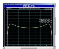
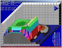
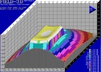
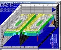
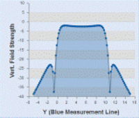
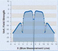
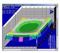
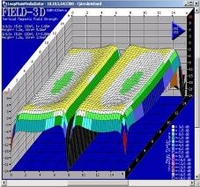
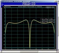
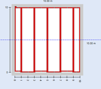
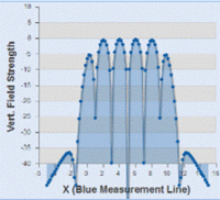
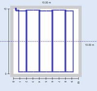
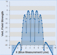
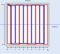
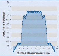
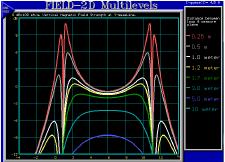
The graph on the right shows the variation of field strength across the centre of a room at a range of listening distances from a perimeter loop. The red curve shows the field strength at a vertical distance of 0.25m from the loop.

In the centre of the room the field strength is -1dB, but at the edge of the room it has increased to over +9dB.

The variation in field strength exceeds that permitted by the standard illustrating why a perimeter loop must not be installed at listening height.

The further the loop is displaced from the listening plane, the flatter the response becomes, leading to some more simple rules of thumb.

  • If the Loop is to be installed in the floor for seated use, (Listening plane of 1.2m) the maximum width of the loop is in the order of 22 metres. (No construction metal present)
  • If the Loop is to be installed in the floor for standing use (Listening plane of 1.7m, the maximum width of the loop is in the order of 26 metres. (No construction metal present)
  • By installing the loop at a greater distance than 1.7m, from the listening plane, the simple perimeter loop can be used to cover larger spaces. This principle is often exploited to cover churches and cathedral size spaces, by installing the loop on the triforium or even externally on the roof.
spill field

2D Plot showing the spill field of a perimeter loop

Remember

A perimeter loop has a spill field 1 - 2 times its width

Spill field is the name given to the signal generated by the system that exists outside of the induction loop.

Magnetic fields fall off very rapidly with distance, however, 1 - 2 times the width of the loop away, a signal level greater than - 32dB may still be present.

That means a loop 5m wide may still be radiating above the acceptable background noise level 5m - 10m away.

Note: - 32dB is the maximum level of background magnetic noise that the standard IEC 60118 - 4:2006 deems acceptable and is used by UnivoxAudio as a reference to define spill control

Remember

Construction metal in the same plane as the loop can absorb the signal.

This absorption or loss of signal is dependent on the proximity of the metal to the loop, the amount and its conductivity. Aluminium is more lossy than mild steel and stainless steel with the highest resistivity causes little or no loss. The phenomenon is also frequency dependent.

To overcome this issue, the first option is to drive more current through the loop and correct the frequency response. With the Power of Univox® and the MLC or tone control featured on all our standard amplifiers, this can work well for small perimeter loops.

The second choice is to move the loop further away from the metal. For example, installing the loop at ceiling level instead of around the floor, assuming that there is no construction metal in the ceiling. A false ceiling using tiles on an aluminium frame may be very lossy depending on its age.

Where the loss is too high and the signal too variable (signal variation across the listening plane is more than 6db), smaller multiple loops must be used if the system is to comply with IEC 60118 - 4:2006.

Note: Metal loss correction is only capable of correcting the frequency response at a single given point. For larger loops, this can mean that some areas will still remain with insufficient compensation whilst others may be over compensated hence the need to use smaller multiple

construction metal in proximity to a perimeter loop will restrict the maximum viable loop width.

If the width of the area to be covered is larger than this a different loop topology should be used

Floor or ceiling Type Max. loop width
Listening plane 1.2m
from Loop
Max. loop width
Listening plane 1.7m
No metal in floor 22m26m
Standard reinforced concrete 6-10m 5m to 9m
Heavy reinforced concrete3-6m2-5m
Metal system floor or Steel deck1-3m 2-3m
Suspended ceiling Glass/Metal 3m3m

Cancellation Loop

A single cable is configured to form 2 loops of different sizes using a figure 8 pattern.

Spill field for Cancellation Loop.

Spill field for Perimeter Loop

Cost effective Spill Control

A cancellation loop is a simple and cost effective way of controlling the spill field in 1 or 2 directions. In its simplest form, it is a figure 8 loop where the ratio of the 2 areas circumscribed by the cable are such that the magnetic fields extending beyond the loop in 1 direction cancel, as shown in the diagram.

This design is simple to install and relatively low cost using just 1 induction loop amplifier. However, the cancellation loop is generally installed in the room so not all of the space in the room will have standard compliant coverage.

Installing a cancellation loop along a second side of the room will reduce the area coverage in the room further, but in some circumstances, it is still more convenient than using Univox SuperLoop Series® technology.

The exact induction loop area ratios to achieve optimum cancellation of magnetic field can be found by trial and error or by using a software based design tool.

Cancellation loops can also be designed using an anti-phase Super 8 (+ -)loop or by driving 2 independent loops with different current values, either by using 2 separate induction loop amplifiers or a custom designed ratio transformer.

Figure 8 Loop

Figure 8 Loop

A single cable is configured to form 2 or more loops generally of the same size using a figure 8 pattern.

The adjacent segments are opposite in phase creating a null field where the sections intersect.

3D - field strength plot

The 3D - field strength plot shows the 2 distinct areas covered by this loop configuration.

field patterns

With both loops of equal size, the field patterns of the 2 segments are a mirror image.

Basic Compensation

In applications where there is significant signal loss due to construction metal or a very large area to be covered, the simple figure 8 loop configuration can provide a cost effective and simple solution.

The standard figure 8 loop is, as you would imagine, a figure 8 pattern of wire. It is made from a single continuous cable and can be 2 or more segments long. It is installed in or on the floor or ceiling.

By dividing the area into smaller, usually equal size segments, it is possible to achieve good uniformity of signal within each segment with a lower drive current. However, since more cable is used, a higher drive voltage will be required.

The voltage headroom of the amplifier and cable type will limit the number and size of the segments in this configuration.

Unfortunately, where the cables of the 2 adjacent segments run next to each other there is field cancellation to the extent that there is a null or no signal for the hearing aid.

In practice, this design is best suited to applications where the seating is fixed in which case, the parallel runs of cable can be kept in the aisles where no signal is required.

This loop design offers improved spill control; along the narrow ends of the loops, the spill is reduced to approximately one loop width, along the other sides, it is 1 to 2 times the loop width. The smaller the width of the loops, the better the control.

Note: The spill field in the horizontal plane is smaller compared to a perimeter loop covering the same total space

Super 8 (++) Loop

Super 8 (++) Loop

Up to 4 separate loop cables are configured to cover the space and connected to a single Univox amplifier in parallel.

field pattern

In the Super 8 ++ Loop configuration, the segments are in phase. The resulting field pattern is identical to a perimeter loop offering the same total area coverage.

2D field pattern

Spill control for the Super 8 (++) loop is identical to the equivalent perimeter loop

The Power of Univox

This loop configuration is a proprietary design unique to Univox® Taking advantage of the higher output current capacity of the Univox® product range. (See Power of Univox®)

On first inspection, a Super 8 loop™ looks like a standard figure 8 loop, creating a similar pattern on the floor or ceiling where it is installed.

However, that is where the similarity ends. Each segment of a Super 8 Loop™ is connected directly to the amplifier ie. in parallel taking advantage of the extra high output current of the Univox® Amplifiers

A Super 8 Loop™ can be configured in 2 ways, either with the segments in phase (++) or antiphase (+ - ) with all Univox® amplifiers capable of driving up to 4 segments.

In Phase Super 8 (++)Loop™ System

The In-phase Super 8 (++) Loop™ system extends the range of the Perimeter loop.

With this configuration, the magnetic field attributed to the conductors running next to each other from adjacent sectors cancel, effectively giving the same performance as a perimeter loop covering the whole space.

Whilst the output current required may be several times as much, significantly, the output voltage equired is reduced by almost the same amount making it practical to cover an area of up to 1800m2 with a single Univox® induction loop amplifier.

Note: The difference in feed cable lengths may cause 1 or 2dB variation in field strength between segments, but standard compliance is still achievable.

Using software simulation Super 8 Loop design is simple, providing affordable solutions for large area coverage

Super 8 (+-) Loop

Up to 4 separate loop cables are configured to cover the space and connected to a single Univox amplifier in parallel.

The big brother of a standard figure 8 loop

As previously stated, a Super 8 Loop™ can be configured in 2 ways, either with the segments in phase (++) or antiphase (+-) with all Univox® amplifiers capable of driving up to 4 segments.

The out of-phase Super 8 (+-) Loop™ system complements the figure 8 loop.

With this configuration, the magnetic fields attributed to the conductors running next to each other from adjacent sectors interact producing a null field identical to that associated with a standard figure 8. The output current required may be several times as much, but the output voltage is reduced by almost the same amount.

Univox® amplifiers all feature a high output voltage, however, due to safety considerations even the largest are limited to 50V. In applications where the impedance of the perimeter or figure 8 loop is too high, a Super 8 (+-)Loop may be a viable alternative.

Design Flexibility

The Super8 loop can be quickly reconfigured from (Super 8 (++) to Super 8(+-). or vice-versa. Furthermore, each individual loop can be driven by a separate amplifier if required, providing the installer with a range of options to optimise the system.

The Super 8(+-) configuration is ideally suited to fixed seating applications where the voltage headroom of the amplifier is insufficient to drive a standard figure 8 loop.

The feed cables can be selected to maintain equal impedance of each loop if required

SuperLoop

SuperLoop<

2 independent figure 8 loops, A master and Slave represented by the red and blue lines.

3D field pattern

The 3D plot opposite shows the field pattern of just one arm of the array.

Spill field

A SuperLoop system can provide excellent attenuation of the spill field

To cover large areas, compensate for the effects of metal and or control spill, a range of different induction loop configurations can be used. The choices are Figure 8 loop, cancellation loop, Super 8 Loop™ and SuperLoop™

The SuperLoop™ exceeds the performance of all other induction loop types in every respect. A standard SuperLoop provides metal loss compensation, large area coverage, ultra-low spill performance, and a highly uniform magnetic field in the vertical and horizontal planes ( when facing the long sides of the loop segments) i.e Near 3D area coverage. The design principles are quite simple and made even easier with the Univox® SuperLoop™ Calculator or our latest software.

A SuperLoop comprises 2 independent figure 8 loops driven by separate amplifiers with a 900 phase shift of the input signal. The larger figure 8 loop is the master loop array and the smaller is the slave array. By applying this phase shift, the associated magnetic fields are uncorrelated ie they do not interact with each other.

Loop Arrays

Uncorrelated Magnetic Fields

Master Loop Array

Magnetic field of Master Loop Array

Note the position and magnitude of the peaks generated by the Master Array

Slave Loop Array

Magnetic field from Slave Loop Array

Note the position and magnitude of the peaks generated by the Slave Array

Master and Slave Loop Arrays

Resultant magnetic field for Master and Slave Loop Array

Note how the 2 magnetic fields combine. The highest wins

Loop Configurations and their properties compared

FeaturePerimeter LoopFigure 8 LoopIn Phase Super 8 LoopTMAntiphase Super 8 LoopTMSuperLoopTMCancellation Loop
DesignSimpleSimpleSimpleSimpleSimple with softwareTrial and error or simple with software
InstallationSimpleModerate1.ModerateModerateHardestModerate
Suitable for large area coverageLimited to a maximum loop width of 22m (n1) YesAs Perimeter Loop (n3)YesYesNo
Suitable for areas with construction metalNo Loop width must be reducedYesNo Loop width must be reducedYesYesNo Loop width must be reduced
Achievable area Coverage100%Null fields where adjacent segments meet100%Null fields where adjacent segments meet100%The cancellation loop limits the max achievable area coverage to approx. 75%
Spill Control1to 2 times loop width1 to 2 x segment width along length of loop.1 x segment length along width of loopsame as equivalent perimeter loopSame as equivalent figure 8 loopExcellent
To 1. 4m in horizontal plane
4m in vertical plane
Depends on design, but only practical for spill control in 1 or 2 directions.
Signal uniformityAcceptable in Horizontal PlaneAcceptable in horizontal plane, but will have null fieldsAcceptable in Horizontal PlaneAcceptable in Horizontal Plane, but will have null fieldsExcellent in horizontal plane and vertical plane (facing the long loop runs)Acceptable in horizontal plane. See 'Achievable coverage'
  • n1 For a field strength variation across the listening plane no worse than 6 db, the maximum loop width for a perimeter loop displaced 1.2m from the listening plane is approximately 22m. Construction metal in close proximity to the loop will dramatically reduce the maximum loop width.
  • n2 Spill control is defined as the distance from the loop at which the magnetic field has reduced by 32dB. (This level is still audible. It equates to the acceptable level of background magnetic noise permitted in the standard.
  • n3 The in-phase Super 8 ( + + ) Loop is limited to the same maximum width for the area to be covered as a perimeter loop

Induction Loop Configurations

Perimeter induction loops are generally the easiest and cheapest induction loop type to install, but due to their constraints:- poor spill performance, restricted size dependent on proximity, type and fabrication of metal structures, field strength variation in horizontal plane etc, They are rarely the best solution and too often, they will not be capable of delivering standard compliant performance.

There is clearly a need for other loop configurations that will meet the demands of real applications. These are:


Here there'll be links in boxes to the different Loop Types

Visit our Shop

Visit our Shop

Visit Our Knowledge Centre

Visit the Knowledge Centre

Contact Us

Contact Us